I never ceases to amaze me that of even the simplest circuits continue to evolve with new variations, requiring just a dose of curiosity and a few extra components if any, waiting to be discovered.
This is the case with the good old 6 transistor Tilden h-bridge which has been used in hundreds of robots. But the application of this circuit can be a learning experience. There are a few variations based on transistor type, active high or low input, input resistor value. The last variable in particular is not often discussed but can have a profound effect on the h-bridge performance.
Motors used in walkers have a highly variable load. A 50 ohm motor may draw 120 ma @ 6V when lifting a the body or stretching a centering spring near the end of leg rotation and yet only draws a few mA at the start of leg rotation when aided by gravity or the tensioned spring.
The h-bridge input resistor is usually the recommended 47K value but should really be chosen to provide the required input current for a given motor. The input current multiplied by the overall h-bridge current gain provides the high peak output currents for the motor at maximum torque. But there is no free lunch: with the input current adjusted for high peak current, energy is wasted when the motor requires less current.
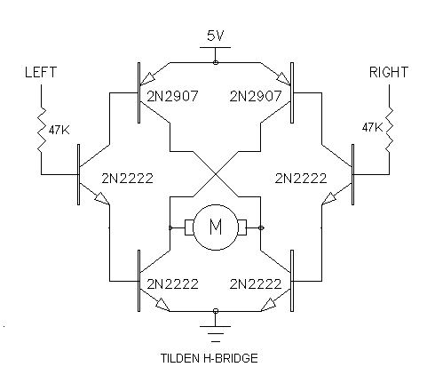
TILDEN H-BRIDGE
Let's follow through the operation of the 6 transistor Tilden h-bridge in Figure 1 :

That input current provides the base current for the input transistor and is multiplied by a factor of about 150 to provide 12 mA of base current to the 2N2222/2N2907 output transistors.
The output transistors have a saturated (<0.6V forward voltage) gain of about 15. This will result in a prospective motor current of about 180 mA at 3.8V which would match the highest current of a motor with a 3.8V/0.180mA = 21 ohm winding. The voltage across the motor is only 3.8V because the output transistors each have a forward voltage of 0.6V .
In this example, the 47K input resistors generate 12 mA of output transistor base current whether it is needed or not. Since this base current does not flow through the motor, it is wasted energy. At low motor currents, more power can be wasted in this base current than the power used by the motor. Simply lowering the base current is not an option as it would give wimpy performance when the motor is under heavy load.
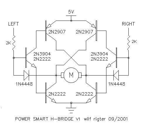
POWER SMART H-BRIDGE
So far we have discussed the conventional 6 transistor h-bridge operation, Figure 2 shows the POWER SMART H-BRIDGEv1 circuit that dynamically adjusts the base current of the output transistors in proportion to the output current.

The principle of operation relies on the fact that the collector-emitter voltage of the bipolar output transistors drops to a very low (deep saturated) voltage when the output current is low. If we could sense that output voltage drop and reduce the base current accordingly, we would provide feedback signal that keeps the base current proportional to the collector current.
The addition of two diodes does just that: when the driver transistor collector voltage drops below 0.6V (start of saturation) the diode starts to turn on and shunts the input transistor base current through the low output to GND. The input resistors can now be made much smaller to provide more base current when needed since the excess input current will be shunt regulated by the diodes if the load is small.
With a 2K input resistor, the input current will be about 2 mA, which if required can easily generate up to 100ma of output transistor base current to provide up to 1000 mA of output load current. When the motor is unloaded, the output transistor base current happily drops to less than 1ma.
Aside from efficiency, the PSH-bridge circuit has another advantage of in that the choice of input resistor is no longer critical. This is convenient with respect using the same h-bridge components for a wide range of motor currents and power supply voltages since the PSH-bridge input current regulator adapts to the circuit conditions as required.
PS H-BRIDGEv1 has one disadvantage that the output transistors have a constant 0.6V voltage drop. That voltage drop affects efficiency as well and is caused by the difference between the 1.2V base-emitter drops and the 0.6V diode drop. An ideal diode drop would be 1V but there is no such reference voltage available.
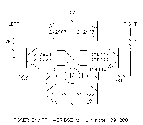
However the improved PSH-BRIDGE v2 in Figure 3 addresses that by adding a 330 ohm resistor in series with the diodes. This resistor has a voltage drop of 500mV generated by the input current which is regulated through the diode when the h-bridge is lightly loaded . This additional voltage drop causes the output transistors to mildly saturate at about 200mV. At higher current the output voltage rises somewhat but remains less than 500mv per transistor at 500ma for a total drop of 1V.


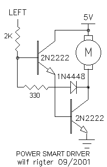
I have tested several versions of the PS H-bridge and the
PS Driver circuits for proof of principle and all work well.
The best performance (so far) was obtained with 2K input resistors
and with 330 ohm resistors in series with the diodes . Additional investigation
will be necesary to put some hard numbers on the relative improvement
in performance of the PS designs compared to the original unPS designs.
enjoy
wilf