Figure 1-Nv Neuron
Wilf Rigter - 06/2001
This paper is about exploring new connections, patterns and behaviors in BEAM Nv circuits with some musings on the meaning of life and everything thrown in for good measure. Beam is the acronym for biology, electronics, aesthetics and mechanics and the mission of beam is to create highly functional, "natural" automata using elegant electronic and mechanical designs. A beam automaton can range from a simple visual display to a robot capable of negotiating an obstacle course. Some of the simplest and most useful electronic circuits are called Nv neurons. Connected in networks, these Nervous neurons are a fundamental building block for Beam designs. The Nv neuron shown in Figure 1 is a very simple circuit building block, which in principle could be constructed with 4 discrete components i.e. two mosfets, one resistor and one capacitor but in practice a network of Nv neurons is more efficiently designed using simple digital CMOS inverter chips.
Mark Tilden and others realized long ago that networks of these simple Nv building blocks could produce complex patterns useful for autonomous robot control, and which introduce an element of "free will" in robotic design if not behavior. Mark and early collaborators explored a large number of designs, some of the most complex of which were described in his Living Machines paper. One observation was that beyond a certain complexity of Nv networks, we seem to get less functionality per circuit element. Conversely the maximum functionality occurs at some critical complexity: no more but also no less complex. As a result of much experimentation, a number of practical Nv network designs were refined using the fewest number of components. A few simple Nv networks are the "core" of most beam designs. Of these the bicore and microcore are the simplest and most common. The operation of the bicore circuit has been analyzed .and described in detail by Wouter Brock in a tutorial, which can be found at http://www.beam-online.com/Bicore_article/select.htm . The microcore tutorial by Andrew Miller is still one of the best and can be viewed at http://www.solarbotics.com/
I would like to build on this work first by looking at the basic
operation of Nv neurons from a new perspective of wave front or
transition logic and second by demonstrating with some experiments
how this can be used in new Nv network topologies. In past
discussions on NV neurons the emphasis has been mostly on parameters
that control the pulse duration. But when connected in a network, it
is the topology or connections between Nv neurons and the waveform
transitions, which determine the actual pulse patterns. So while Nv
neuron timing parameters control pulse durations, it is the edges or
transitions of pulse waveforms, that trigger or reset the active
state of Nv neurons in a network. It can be said that pulse patterns
are generated by the order and the logic by which a network
"processes" these transitions.
What's all this Nv stuff anyhow?
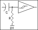
A basic Nv neuron consists of a R/C differentiator followed by a
voltage gain block (usually a CMOS Schmitt inverter) to square up the
differentiator output. The Nv neuron circuit may look familiar as it
is found in most CMOS data handbooks as an example of a simple edge
detector or one-shot or mono-stable circuit application. Indeed, it
was well known that such circuits could be used in series to
generate, a sequence of pulses. In recent years, there has been a
trend towards using micro-controller chips as a universal building
block for generating control sequences. However for simple, low
precision applications, the analog approach can be effective both in
cost and development time.
Figure 1-Nv Neuron
When two or more Nv neurons are connected in a network, we can
create a self-sustaining pattern generator that is simple to
interface to sensor inputs, which react to the environment, and to
simple connect to small motors, which provides the action and
mobility for an automaton. There are several variations of this
network, all of which belong to a class of circuits better known as
"relaxation" oscillators. Ironically the behavior of relaxation
oscillators is anything but relaxed and the Nv neuron is more
appropriately referred to as a "nervous" neuron. Unlike the precise
and predictable timing of a micro-controller, the operation of an
analog pattern generator shows variability, complexity and at times
chaotic behavior. Despite the fact that Nv networks are hardwired,
the non-linear nature of the circuit allows it to be "programmed"
with new behaviors by adjusting or tuning the Nv network. Since
sensors also affect this adjustment and this gives rise to a kind of
fuzzy logic that can adjust behavior in changing environments. The
pulse patterns are controlled by:
1) The parameters that control the duration
of the Nv pulses
2) The topology of Nv connections or logic
of the network and
Each Nv neuron in a network controls the width of it's output pulses by its timing resistor and capacitor values, which can be easily modified by external input from sensors. Repeating output pulses can be used to control the speed and direction of motors. When used in an automaton, the Nv network responds to the changes in sensory inputs by controlling motor speed and direction, which in turn changes the position of the sensors. As a result of feedback from the system as a whole, the duration and effect of Nv neuron pulses take on a certain complexity and variability and the active state of a Nv neuron is therefore referred to as a "process".
Another parameter that introduces pulse variability is incidental internal electronic feedback. This feedback may come from conducted electrical noise generated by the motor or through power supply loading as it reacts to a mechanical load and this "interference" in turn can cause thresholds or timing waveforms to "dither" and generally shorten the pulse duration.
Yet another type of electronic feedback uses coupling components between process outputs of one network and inputs of another network. In this type of "master-slave" arrangement, the processes of one network influence the processes in another in harmonic phase locking and sometimes chaotic relationships.
One Nervous Neuron, a Network doth not make
A nervous neuron, as the name implies is sensitive to sudden change at its input. An Nv neuron's response to input change depends on the polarity of the input signal, the resistor reference voltage, the gain and signal inversion of the output stage and the current output state of the neuron. Nv neurons respond to rapid voltage changes at their inputs and in turn generate rapid voltage changes at their outputs. These rapid voltage changes mark the leading and trailing edges of the voltage pulse we call processes. In Figure 2, we show the incoming process pulses at point A and the Nv generated process pulses at point C. The exponential (saw-tooth) waveform at point B is the charging voltage at the midpoint of the resistor and capacitor at the input (or bias point) of the Schmitt trigger inverter. The Nv output changes state when the bias point voltage crosses the Nv trigger and reset thresholds. The voltage level of the trigger and reset thresholds are shown as the upper and lower dashed lines respectively. The Nv generated process is triggered with a positive edge signal at point A. The N process can be reset, either from the internal R/C time constant, when the voltage at the bias point crossed the lower threshold or externally, from a negative edge on point A. Once the Nv output is reset, a negative edge on point A is ignored or blocked. The basic Nv pulse width for a 74HC14 Schmitt Nv can be simply calculated as T=RC.
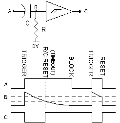
Figure 2 - Basic Nv Neuron Timing
Seeing is Believing
The output state of an Nv can be observed by connecting a LED and resistor to the Nv output pin. . With the very slow propagation of single process pulses, LEDs and our eyes are sufficient to study the interaction of Nv neurons. What happens when an Nv network in a state of saturation or hyper-saturation is much more difficult to observe using just LED indicators. Since the pulse propagation in a saturated circuit is very rapid, we must be able to record fast changing events and play them back in slow motion: i.e. you'll need some kind of oscilloscope. For those of you not familiar with oscilloscopes, these are instruments that amplify, record and display voltage levels as traces on a screen. Older analog oscilloscopes use the persistence of a phosphorescent coating on the inside face the cathode ray tube as a temporary storage medium excited by a fine beam of "cathode rays" deflected vertically by the amplified external input signals and horizontally by the internal time base signal.
Like a PC soundcard recording audio voltage signals, a modern digital storage oscilloscope can convert voltage waveforms from analog to digital form, store this data in memory and display multiple traces showing the time relationship between concurrent events to a few billionth of a second. Even though it has a more modest digitizing speed of 44,000 samples per second, a PC sound card together with the bundled software can also capture circuit waveforms and show them as graphical voltages traces which is a powerful way to analyze circuit behavior. To aid the reader in visualizing circuit behaviour, I generally attach sample traces for each circuit of the voltages measured at key nodes and outputs of the network. The voltage is plotted as a vertical displacement of the trace over an interval of time on the horizontal axis. In a manner of speaking, these oscilloscope traces provide a brief history of the Nv output states with the oldest information on the left hand side of the trace
Transition Rules, ok?
The term Very Slow Propagation Artificial Neural Systems (VSPANS) was used as an early description of Nv networks. It implied that the pulse propagation was limited by pulse or proccess durations. When attention is given to process transitions, which can traverse the entire network in a matter of a few nanoseconds, it is clear that the term VSPANS may be a misnomer.
There is a simple set of rules derived from the Basic Nv waveforms
in Figure 2 to predict the response of Nv neurons to signal
transitions which can be used to understand the behavior of processes
in Nv networks from single process propagation to hyper-saturation.
For the commonly used grounded inverting Nv neuron such as shown in
Figure 2, the transition rules are as follows:
1) TRIGGER - If the Nv output is high, then a rising edge or
positive transition at the input of that Nv is propagated as a
negative transition by setting that Nv output to low for the duration
of the Nv R/C time constant or an external reset transition (which
ever comes first).
2) TIMEOUT marks the end of the process R/C time constant when
the slow falling edge of the charging voltage of the capacitor at the
inverter input crosses the RESET threshold. The Schmitt input causes
the Nv output to rapidly change and generate a single positive output
transition.
3) RESET- If the Nv output is low (i.e. active process), then a
falling edge or negative transition at the input of the Nv terminates
the active process and is propagated as a single positive output
transition.
4) BLOCK - If an Nv output is high, then a falling edge or negative
transition at the
input of that Nv is blocked and not propagated.
You may wonder about another possible rule: If the Nv output is low,
then a rising edge or positive transition at the capacitor input
would be blocked but this state does not occur in a grounded resistor
Nv.
Processes and Network Logic
The positive and negative going edges or transitions of processes
can propagate through one
or more neurons in a network depending on the state of Nv neuron. The
Nv neuron can be in the REST state (high output) or in the PROCESS
state (active low output). In the design of a Nv network, the logic
for transmission or blocking of transitions is as important as the
generation of processes. The PROCESS or active state duration is set
by the R/C time constant of the differentiator and can be controlled
by external factors. The duration of each process can be influenced
by several external sources:
1) Sensors
2) Control voltage or current
3) Noise feedback.
Sensors generally change the time constant with variable resistance elements that are sensitive to position, tactile, photo, temperature, pressure input. The time constant can also controlled by changing the R reference voltage or by injecting current into the bias point of the RC network.
One commonly used network has four of the inverting Nv neurons
connected in a loop. The microcore or 4Nv loop is shown in Figure 3.
The operation of in the single process mode of the microcore circuit
is fairly intuitive. The single process consists of an active low Nv
output pulse, which moves from one Nv to the next with the duration
of each output pulse determined by that Nv timing components. The
pulse "moves" when the end of one Nv process triggers the start of
the next Nv process. This simple sequential pulsing of the Nv outputs
is used to control motor drivers, which cause motors to turn in a
specific order and direction to provide the appropriate "muscle" for
our robots. The sequential pulsing of the Nv outputs shown in the
Figure 3 (one process) traces depicts the normal operation of a 4Nv
microcore circuit
.
Figure 3 - 4Nv network
The "One process" oscilloscope trace in Figure 3 shows a single,
mutually exclusive, active low process pulse propagating through the
loop of 4 Nv stages. That means at any time 3 outputs are in the
inactive high output state and only one is low. The transition logic
that applies to the single process condition are as follows:
1) Assume that the Nv1 output generates a positive transition at the
end of the active low output pulse as a result of TIMEOUT.
2) The positive edge of the Nv1 output is applied to the input of
Nv2, which currently has a high output and will therefore TRIGGER to
generate a negative edge at its output. (High to Low).
3) The negative edge of the Nv2 output is applied to the input of the
Nv3 stage which has a high output and will therefore BLOCK the
propagation of the transition.
4) When Nv2 output generates a positive transition at the end of the
active low output pulse as a result of TIMEOUT which is applied to
the input of Nv3
5) This sequence repeats for each Nv.
RESET never occurs in this sequence since the condition of a negative
input transition to an Nv with an active low output is specifically
excluded in this case.
Saturation and Hyper Saturation
It is possible to have more than one active process in a microcore. For example a microcore network normally starts up with two processes. An Nv network is "saturated" when a maximum number of processes are circulating in the network. The limit of the maximum number of processes in a given number (n) of series connected Nv neurons is integer n/2 processes. That would mean two processes circulating or 5 Nv neurons or 3 processes circulating in 6 or 7 Nv neurons, etc. This idea of saturation being multiple processes is apparent from observing the output states with an LED and follows the conventional wisdom about what happens inside these networks. What really goes on is that waves are racing around the loop faster than a speeding bullet and in fact there are always only two independent processes present in any saturated Nv core of which only one is "active" at a time. The existence of such fast waves is even more strongly evidenced by the elusive condition known as "hyper saturation".
In the saturated traces of Figure 3, the 4 Nv stages of the microcore) there appear to be two output pulses active low at the same time. Observing the LEDs of a microcore would lead you to believe that these two pulses are circulating through the network in much the same way as a single process. In fact, a single TIMEOUT transition at the output of one Nv neuron propagates rapidly through all Nv stages until it arrives back at the input of that Nv. To explain this with the transition logic, observe that at any time two outputs are low and two outputs are high. Further let's assume in the current state of the microcore, Nv1 and Nv3 are low and Nv2 and Nv4 are high.
1) Assume that the Nv1 output generates a positive transition at
the end of the active low output pulse as a result of TIMEOUT.
2) The positive edge of the Nv1 output is applied to the input of
Nv2, which currently has a high output and will therefore TRIGGER to
generate a negative edge at it's output. (High to Low).
3) The negative edge of the Nv2 output pulse is applied to the input
of Nv3, which currently has a low output and is therefore RESET to
generate a positive edge at it's output (Low to High).
4) The positive edge of the Nv3 output is applied to the input
of Nv4 which currently has a high output state will therefore TRIGGER
and generates a negative edge at it's output (High to Low).
5) The negative edge of the Nv4 output is applied to the input of the
Nv1 stage which now has a high output and will therefore BLOCK the
propagation of the transition.
All Nv outputs change state virtually simultaneously! Initiated
by the TIMEOUT of the Nv1 process, the transition propagates around
the loop in a few tens of nanoseconds to TRIGGER and RESET the other
Nvs in the network and then is finally BLOCKED at the input of Nv1.
What happens next is even more interesting. The new state of the
microcore is Nv1 and 3 high and Nv2 and 4 low so the next fast
propagating edge is determined by whichever of Nv2 or Nv4 has the
shorter time constant and first times out. Nv2 does not necessarily
follow on the heels of Nv1. The simple model of "the end of one Nv
process triggers the next Nv" breaks down when trying to explain the
saturated condition. The transition logic accounts for the Nv circuit
unsaturated and saturated behavior by the dynamics of process
propagation. It is important to be aware of what controls the
pulse widths of the various output pulses in an Nv network in the
saturated condition as some prior discussion suggested that inducing
saturated patterns might be useful for altering gait etc. In
saturation, a Nv core will have multiple output pulses but these are
copies of only two processes, that each generate a transition that
propagates through all Nv stages always initiated by one even and odd
numbered Nv which has the shortest time constant.
We have shown that the slow propagation mode is an exceptional case of transition propagation. The contrasting views of transition logic and VSPANS is even more striking when we consider hyper-saturation in Nv networks. This condition is thought to be elusive and rare in Nv networks but it is is actually a common but rarely recognized condition in Nv loop networks. The condition is characterized by a faint glow of all LEDs in a Nv loop and a sharp increase in the CMOS power dissipation. Often the circuit is thought to be "locked up". If we turn to transition logic rules, it is clear that a case can exist in which a saturated circuit propagates a transition through the network at high speed without encountering a Nv neuron in a state where BLOCK rule would normally apply in which the transition propagation is halted. That state is in fact the normal start up condition for all odd numbered Nv loops (ie 50% of all possible Nv loops) in which the sum of all Nv inversions is odd or inverting. In hyper-saturation there are no processes as such in the loop but only one edge circulating (like a Mobius loop) with one net inversion around the loop. In this condition, the network acts as a single oscillator with the sum of the loop delays equal to one half period of oscillation. For example, a 5Nv loop of 74HC14 inverters, each with a propagation delay of 13ns will oscillate at about 7.5 MHz. Hyper-saturation can also occur as multiple out of phase transitions in even number Nv loops. For example a 6Nv loop can be seen as having two 3Nv loops connected in series. The proof of this is found in measuring the frequency of oscillation, which for a 6Nv neuron with two transitions in hyper saturation is 12MHz, which is the same frequency as a three Nv neuron loop with a single transition. So in hyper saturation, the networks act as resonant cavities for transitions. A similar principle is often used in frequency multiplying crystal oscillators operating in the overtone mode. It may be possible to dynamically control the number of transitions in a hyper-saturated network or one can contemplate complex networks in which edge synchronization can control information flow. For now, it is enough to be aware of the existence of hyper saturation in Nv loops and keep in mind it's potential applications.
Looping and Branching Nv networks
The bicore, microcore and all other networks described so far were
all loops with the output
of the last Nv neuron connected back to the input of the first Nv
neuron. A Nv network does not have to be a loop to process
transitions observe the circuit of Figure 4, in which 6 grounded Nv's
are connected in series but are not looped back.
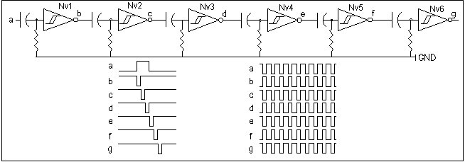
This network is usually called an Nv branch. To describe it's behavior, assume that all stages are in the rest or inactive condition. All outputs are high and a single rising edge on the Nv1 input causes a pulse on Nv1 output, which propagates slowly from stage to stage through the 6Nv branch until the last pulse in Nv6 terminates. In order avoid the Nv1 input pulse from affecting the Nv1 output pulse the input pulse width must be longer than the Nv1 time constant. Several pulses may be injected into the input and will propagate independently from Nv1 to Nv6 as long as the RESET rule does not apply.
When the input waveform positive and negative pulse width are shorter than the shortest even and odd Nv time constants, Rule 3 will cause saturation with the positive and negative transitions at the Nv1 input propagating to the Nv6 output in nanoseconds. This is clearly seen in the right hand traces in Figure 3, in which the Nv1 input is driven with waveform with pulse widths shorter than the shortest Nv time constants. This results every Nv output generating a true or inverted copy of the Nv1 input waveform with a delay of a few tens of nanoseconds separating the transitions from Nv1 input to Nv6 output. In that condition, a saturated 6Nv branch generates as much pattern data as a 2Nv branch since only the shortest time constant even and odd Nv determine the pulse width of all other even and odd Nvs.
Nervous Neurons have Resistor Inputs too!
We have discussed the popular grounded Nervous neurons so far and it should fairly intuitive that a Vcc referenced Nv neuron would behave the same way although the active state and the transition logic rules then apply to oppposite input and output polarities. It is also possible to design networks that use Nv neurons with different resistor reference voltages. Take a look at Figure 5, a 6Nv branch with alternate gnd and Vcc referenced Nv stages. Initially, all Nv's are inactive with alternate high and low outputs states but now, a external waveform with a positive edge at the input of Nv1 propagates rapidly through all stages to the Nv 6 output and then, after a delay, the circuit reverts back to its original state as Nv time constants time out and one or more Nvs change state depending on what position in the branch they occupy. If the output were connected back to the input, a saturated condition would occur. Or would it? Is it possible for this network to have a single process?
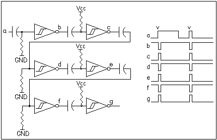
Figure 5 - Mixed Vref 4Nv branch
To Invert or Not to invert
Early relaxation oscillators were commonly designed with inverting transistor gain stages using the same basic topology as the grounded or Vcc referenced inverting bicore. The non-inverting Rigter bicore circuit in Figure 6 shown side by side with the classic inverting grounded Bicore is actually quite unusual. It can use non-inverting buffers such as the 74HC244 or 74HC245 with one grounded and one Vcc referenced resistor. In both bicores, the duty cycle of the output pulses determined by the ration of R1/C1 and R2/C2 time constants. The non-inverting bicore lacks the complementary (inverted) output which makes it somewhat less versatile.Yet it provides an option for designing an oscillator using some spare non-inverters rather than adding another inverter chip.
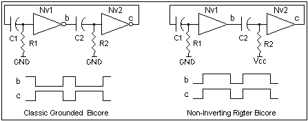
Figure 6
Think Global, Act Local - Distributed Feedback
The problem with saturation would seem to be the RESET rule, in which an active Nv output is reset by an input transition. What if we make the Nv non-resettable so that it is not subject to those pesky transitions that cause the Nv to reset and lead to saturation. The circuit in Figure 7 does just that.
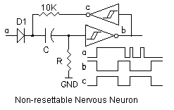
Figure 7
The timing traces show that an active low signal pulls the input
low through d1 and causes output b to rise and this triggers the Nv
stage on the positive edge. Nv output c goes low and holds the input
of the first stage low through Ra as long as the Nv stage is active.
This positive feedback means that the Nv stage cannot be reset nor
can it be re-triggered until it has timed out. This local feedback
principle can be extended to several stages. In Figure 8 we
show a mixed Nv network in which a saturated state is triggered
when input "a" goes low. A negative edge causes a fast
transition to propagate through all Nv stages and flips the output
states as shown in trace a-g. Then a series of pulses or processes
are generated in reverse order. Each Nv except for Nv6 receives
positive feedback as was the case in stage one of Figure 7 . Nv6 is
referenced to ground and will time out as shown in trace g. When Nv 6
times out, its output goes high and enables the Nv5 stage to time
out. This process repeats with each Nv timing out sequentially and
reverting to its inactive state as shown in traces f-c. Note that the
outputs pulses are alternately inverted. The last stage to time out
is Nv2 in trace c and it's pulse width is equal to the sum of all
other Nv stage time constants.
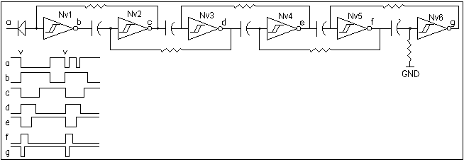
Figure 8 - Forward Saturation / Reverse Single Process 6Nv Branch
In Figure 9 we create yet another type of "central pattern
generator" with the same unusual pulse sequence as the mixed 6 Nv
branch circuit as Figure 8 but with an embedded grounded bicore
input stage.
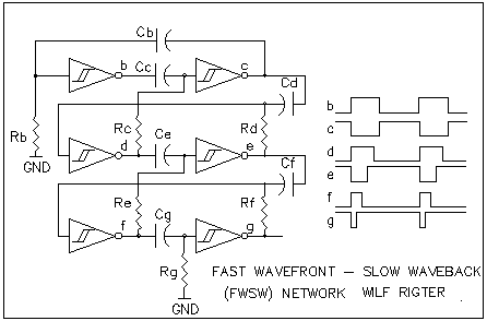
Figure 9- Fast Wavefront Slow Waveback Network
Again the positive leading transition on output b propagates almost instantaneously from the first stage to the last and then reflects and slowly propagates from the last Nv stage back to the first Nv stage. The pulses widths generated at each output are determined by the sum of the Nv time constants from front to back stage. So far I have used this circuit only for lighting LEDs. In a bar graph of 5 LEDs they all light up instantly as the fast transition propagates and then slowly extinguish each LED one by one as the wave propagates back.
A 2D Nv Network Example
A more complex example of 2D transition logic is shown in Figure 10 - the NxMatrix. The general requirement for self-starting oscillation in any array is negative DC feedback. In this design, the connections through the resistors and inverters are such that the sum of all inversions is odd. The general requirement to reduce the possibility of hyper saturation is positive AC feedback but there are other ways to suppress hyper saturation by adding a small capacitor from any output to ground.
The Nx Matrix is an experimental design that meets the DC feedback requirement so it will oscillate. No traces are shown because I have not yet analyzed the possible process conditions. The more complex networks can theoretically have many more patterns and the transition logic rules may be difficult to execute manually. The good news is that the set of rules are a simple algorithm and the other physical parameters such as propagation delay and time constants are relatively easy to model. So in order to predict the behavior of complex networks one can execute a simple computer model and use a screen display to indicate the possible output states. Alternately, the circuit could be prototyped and the starting parameters can be entered with the State Injection Circuit (SIC).
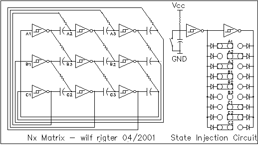
Figure 10 - Nx Matrix and State Injection Circuit
This would experimenters to determine useful starting conditions. An
improved version of the state injection circuit would permit the
initialization of several useful starting state states using
hardwired 74HC240 pattern memories that are normally tri-stated and
one of which is enabled at a time as required. Be aware that
injecting a particular states makes it the inverted state available
in the next DC coupled Nx stage, so the number of HC240 outputs
required to inject any possible starting state is not likely to be
more than 8.
Order and Chaos? That is the question!
Complex physical systems from global climate systems to automobile
traffic flow, to heart muscle contractions exhibit periodic, harmonic
but also "unpredictable" behavior called chaos. This is perhaps not
surprising given a large number of loosely coupled elements and the
difficulty calculating or controlling their precise relationships. It
maybe somewhat unsettling to find chaos in very simple mechanical
systems such as a double pendulum whose complex behavior can give a
remarkable insight into the simple sources of chaos (http://www.cs.mu.oz.au/~mkwan/pendulum/pendulum.html)
It also easy to find chaos in simple electronic circuits. Until a few
decades ago, engineering has always attempted to eradicate chaotic
behavior from control circuits. After all chaos implies loss of
control and control is what engineering is all about. Scientific
investigations into chaos during the last century have revealed that
in natural and biological systems, order and chaos are finely
balanced in an efficient adaptive dynamic symphysis in which patterns
and order emerge and are maintained through chaos under dissipative
non-equilibrium conditions. In a recursive sense, a new paradigm has
emerged in which chaos is not the evil dark side but a fundamental
and essential cornerstone of the natural order. In order to
understand some basic concepts of chaos and it's constructive role in
the scheme of things, I suggest starting here: http://pespmc1.vub.ac.be/CHAOS.html
and
http://arti.vub.ac.be/chaos/alife/articles.html
In electronic circuit designs, chaos is often observed but rarely
recognized as useful. When an LC oscillator uses a non-linear
negative resistance gain stage, small adjustments in the transfer
characteristic can result in the generation of: a fundamental tone,
then progressively lower sub-harmonics with the onset of each
sub-harmonic accompanied by a region of instability (chaos) which
rapidly escalates as the bifurcations become close and finally
breaking up into white noise. This can be demonstrated in a simple
circuit called a Chua oscillator shown in Figure 11.
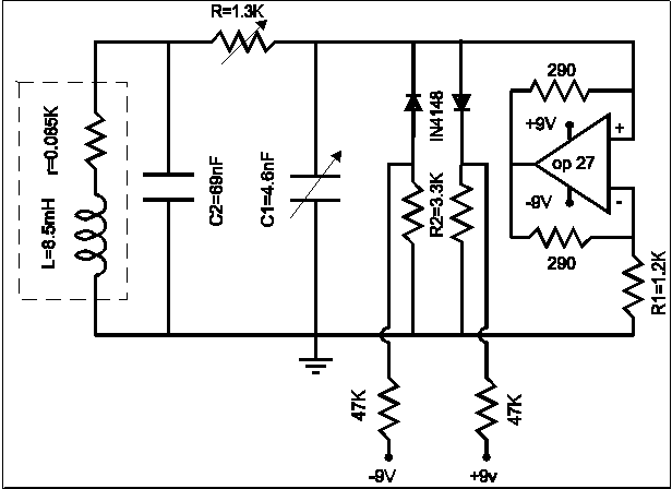
Figure 11 - Chua's Chaos Generator
The LC tank circuit provides the basic frequency, diodes represent
the non-linear term and the operational amplifier is connected as a
negative resistance. The circuit initially oscillates at a
fundamental frequency but when the potentiometer is adjusted, the
circuit introduces sub-harmonics in a series of bifurcations. The
point of bifurcations introduces uncertainty and this shows up at
that adjustment as chaos. The number of bifurcations increases
rapidly with further adjustment and from the 6th bifurcation on the
circuit becomes completely chaotic. The waveforms produced by this
and similar circuits can be used in a wide range of applications to
test or inject chaos in other circuits to data encryption , to
generate music as shown for example here:
http://www.ccsr.uiuc.edu/People/gmk/Papers/IEEE/ieee52da/ieee52da.html
and http://www.computermusic.ch/files/articles/Chaos,Self-Similarity/Chaos.html
A quite different circuit using linear operational amplifiers,
taken from J.C. Sprott's - A New Class of Chaotic circuits
( http://sprott.physics.wisc.edu/pubs/paper244.pdf
) consists of 3 integrators, which remarkably also exhibits chaotic
behavior.

Figure 12
The circuit is not much different from the Nv and Nu circuits and further investigation will be needed to confirm if the oscillation in Nv/Nu cores can be induced to operate in chaotic orbits. To find chaos in a simple equation and in such simple designs may give some pause to reflect on the pervasiveness of chaos.
The link of chaos with neural networks is important because they too can exhibit a rich and complex variety of non-linear dynamics of which we should be aware in our attempts to emulate biological control systems. Instead of providing us with simple deterministic control, these analog networks can exhibit behavior that is erratic or chaotic. Long considered as the antithesis of engineering and control, the essential chaotic nature of the world is now being explored for the understanding and solutions it may offer to what were previously intractable scientific and engineering problems. Humans are capable of highly abstract thinking by manipulating models of reality. If our model of reality is to be more complete, we must learn to better understand the synergistic duality of order and chaos and how it changes our perception of the world.
The Future of Nervous Neurons
There is a class of computer generated objects called Cellular
Automata (CA) which are virtual cells each of which behaves in
accordance with a few simple rules of interaction between that cell
and it's neighbors. Since many cells can interact, they form colonies
that exhibit a highly complex group behavior. John Conway's Game of
Life is an early example of CA whose on/off state is simply displayed
as light and dark pixels on a computer screen. In a system of
sufficient complexity (e.g.256x256 cells) wonderfully complex
self-sustained dynamical patterns emerge from apparently random
beginnings. Despite the way in which cells seem to compete or
cooperate, each is still controlled locally by a simple algorithm as
the expression of a kind of digital DNA to process and
control the flow of information in these colonies. A good
introduction is found here http://lcs.www.media.mit.edu/groups/el/projects/emergence/
or here http://math.hws.edu/xJava/CA/
The cellular automata can themselves be used be used to create
computers, model gas flow and and other systems physical systems the
real world. A group at MIT have designed a digital
CA engine (CAM-8) http://www.im.lcs.mit.edu
. Also check out the work being done at the Santa Fe Institute
http://www.santafe.edu/projects/evca/
While an analog beam circuit design equivalent to CA has so far been
elusive, there are tantalizing hints of such dynamical group behavior
in neural networks
In BEAM, we encourage an approach to technology using a wide spectrum of ideas from all disciplines of science and technology. For example, when designing adaptive or learning robots, we can take lessons from the way babies learn to move and control their bodies. At that young age there is no abstract systematic analysis of body motion. Instead the body and nervous system provide a general solution to learning using random motion and cognitive associations (e.g. pleasure and pain) as a trial and error means to shape cause and effect into an internal model of the world.
We can also look a the way that far from equilibrium systems in which stable regimes can evolve out of chaos based on a few simple rules. For example, the global "water cycle" depends on the physical behavior of that simplest of molecules, H2O, and it's complex phase changing dance with the sun. In the current climatic phase, this far from equilibrium system operates in a relatively stable macroscopic regime of oceans, vapor, rain, snow, glaciers, all part of what appers to be a carefully crafted natural solar engine for the capture, transformation, storage and distribution of solar energy that makes life, as we know it, possible. One tiny aspect of the nature of water is the formation of ice crystals into a large variety of beautiful symmetrical shapes but no program or microprocessor is used here. Yet the formation of crystals can have a profound effect on life as we know it for example by the role of water crystals in the maintenance of the upper atmospheric ozone layer. It is the macroscopic behavior of uncountable individual molecules interacting with each other in accordance with simple rules that give rise to the various states of H2O. And lest we forget, our human bodies are primarily H20.
By studying natural processes and natural systems and how they evolve, we may expand our way of thinking about designing and programming robots e.g. ideas for growing or evolving networks that control robots. It is not just BEAM , but any science, technology or engineering discipline which can benefit from understanding the role it plays in the scheme of things, and that understanding comes from observing and studying the world from the broadest possible multi-disciplinary, integrated perspective.
On a much smaller down to earth scale, a few years ago, while searching for electronic equivalents of CA I discovered BEAM and was immediately struck by the potential of BEAM circuits to be combined into networks which give rise to kind of macroscopic behaviours that CA exhibits. While I have not yet achieved that goal, being somewhat sidetrack by the many interesting ideas of others, my understanding and ability to design and apply these circuits has improved a lot. So far nothing suggests that my objective cannot be reached using this simple technology. And so I will enjoy continuing the search for useful Nv circuit topologies, patterns and behaviours, so stay tuned!
wilf