The first BEAM circuit I ever laid my eyes was a Solar Engine I saw in a magazine article 6 or 7 years ago. I remember that it was an early Type 1 Zener SE designed by Mark Tilden. I also remember my surprise at reading the description of the solar energy concentration concept and the utter simplicity of the design. Other than that, I was woefully unaware of Mark's other work and it would be another 3 years before I discovered both the list and the other legendary BEAM circuits.
As is the case in any evolving technology, The Zener SE was neither the earliest nor the most efficient of the type 1 Solar Engines. There were other transistor SE designs and I even remember a relay SE design but none has captured the essence of the small autonomous solar power plant as well as these BEAM circuits.
The Zener SE was tricky to use: it draws significant current just before triggering, it requires fine tuning of the resistor for different motors and operates reliably only over a narrow range of light levels. The Zener SE has been superseded since then by other circuits, in particular the simple efficient 1381 SE and more recently, the Miller Engine endure as the main SEs for BEAM applications. The Chloroplast SE is also popular but uses a MC34164 voltage detector and needs more current during charging.
The 1381 Solar Engine
Ironically, the CMOS 1381 voltage detector was originally designed for resetting CPU chips. Replacing the zener in the SE with a 1381 was a big improvement over the previous design providing very low standby current during charging, a stable trigger threshold voltage and a fast "snap on" output signal.
The 1381 SE uses the voltage detector for triggering and then latches the ON state with a SCR like circuit using a PNP and NPN transistor. After triggering the 1381 is no longer active and the latch circuit resets when the voltage on the capacitor drops below about 1V. This is the major shortcomings of the 1381 SE : the low reset voltage of the latch that causes the main capacitor to be almost completely discharged with little or no useful power supplied to the motor during the last part of the discharge cycle and a long recharging time. In my comparative SE testing, I also discovered that the 1381 SE can hang up at the end of discharge if the latch fails to reset. The latch circuit is needed to keep the SE circuit active, after the 1381 triggered because the 1381's own reset voltage is very close to the trigger voltage and the slightest voltage drop on the main capacitor would reset the 1381 almost immediately.
The ideal type 1 SE would have independent trigger and reset voltage levels. The difference between the trigger and reset voltage is called the hysteresis voltage. The 1381 has a build in hysteresis voltage of 50-100mV.
The Miller Engine
The Miller Engine uses an elegant solution by increasing hysteresis of the 1381 using a 1N4148 diode between ground and in the 1381 ground pin. The voltage across that diode raises the trigger voltage of the 1381 by about 250mV. A small capacitor is connected between the 1381 power and ground pins to suppress oscillation and maintain the voltage across the 1381 during the critical interval when the motor turns on and the supply voltage drops. The capacitor is normally 0.1 to 1.0uF but larger values can be used to increase the ON duration. The trigger voltage is the sum of the rated 1381 voltage plus 250mV and the reset voltage is equal to the 1381 rated detection voltage. The 1381 output signal is about 5ma and can drive the base of a NPN transistor such as the 2N3906/2N2222/ or my favorite the Zetex ZXT449. The collector of the NPN transistor is connected to the motor or other load.
While the Miller engine is very simple and reliable it has a few problems: since the gnd pin is not at ground but at 250mv the output voltage is also at 250mV. That's ok since a transistor won't start to turn on until you get to 500mV. But it means that there is no easy way to increase the hysteresis voltage of the Miller engine by raising the diode drop without also adversely affecting the 1381 output voltage .
There are other well less know designs which try to address that.
For example, the Hyper Popper circuit provides separate trigger and reset voltage levels by using two 1381 voltage detectors and a latch. This makes it too complex and expensive unless tight control of those two voltage levels is a must.
I have previously tried my hand at 1381 SE designs and the Variable Threshold SE (VTSE) design was a reasonably successful solution. However the VTSE uses a resistor divider across the capacitor which increases the standby current during charging.
The 1381wr SE
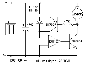
Not quite as catchy as the Miller Engine, the 1381wr SE shown in Figure
1 uses a similar number of parts and also has that "now why didn't I think
of that before" feel to it.

It is very similar to the 1381 SE with two critical differences:
any number of diodes or LEDs can be added in series with the 1381
to increase the trigger level up to 5V while the reset level
is equal to the rated reset voltage of the 1381. The other change to the
1381 SE circuit is to connect the PNP collector to the 1381 power pin instead
of directly to the NPN base. As a result, the combined diode/LED
and trigger voltage must be exceeded before the 1381 triggers and it's
output goes high. The output is connected to the NPN base and when the
NPN transistor turns on, the collector voltage drops to GND. The resistor
now supplies base current to the PNP transistor and it turns on to bypass
the diodes/LEDs and to connect the 1381 directly to the capacitor V+. The
1381 then remains on until the voltage drops below the 1381 reset voltage.
While the SE is reset and charging, the 1381 output is solidly at ground
to keep the NPN or power mosfet output transistors firmly turned off.
When the SE is triggered, the 1381 output rises to the capacitor V+ which
can be as high as 5V to drive a NPN base with high current or a power mosfet
with a high gate voltage. If the gate voltage is not sufficient, the same
solution as used in the Miller Engine, with a photo voltaic diode between
the 1381 output and the mosfet gate, can be used.
The capacitor value, the solar cell voltage, the number of diodes and/or
LEDs and the output transistor can all be chosen to suit your particular
application.
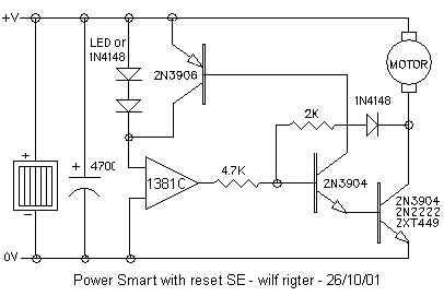
The result is a robust design that can drive any load as well as the Miller SE but has a wider range of hysteresis voltages to chose from. I have tested it with a range of loads from lens motors to walkman motors to toy motors and all work equally well. The design can be adapted to bigger loads such as the B.I.O. Bug gear motor using the efficient PS1381wr SE with the ZXT449 transistor in Fig 2

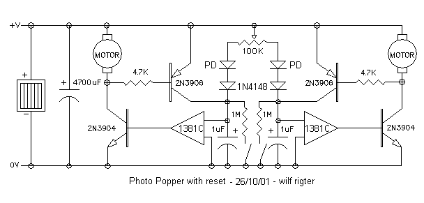
or the classic photo popper circuit can also benefit from the lower voltage drop on the main cap, less wasted current draw and shorter charging times with the PhotoPopper-wr SE design shown below. The 1N4148 diodes are optional as are the tactile switches added across the capacitors as per the original photo popper design.

Anyway I hope you will enjoy using this updated version of the 1381 Solar Engine in your next project and remember your comments and feedback are highly appreciated.
wilf